Isolators: Considerations for Shock and Vibration Requirements
Isolation systems or isolators can be used to:
-
Reduce the effects of externally generated shock and vibration energy from negatively affecting the performance of electronic equipment
-
Reduce the amount of structure-borne noise transmitted from electronic equipment into the surrounding structure or ship’s hull
Many isolators fall into the latter category, and while they may reduce transfer of vibration energy between the enclosure and the surrounding structure, they are not suitable for meeting the strict performance requirements called out in MIL-S-901D (Shock) and MIL-STD-167 (Vibration).
There are a number of isolator options available with isolators that vary in performance, material, size, durability and cost. A brief discussion of each of these options will allow customers to select the best-value isolation system.
Performance — An isolation system intended to reduce the effects of externally generated shock and vibration energy from negatively affecting the performance of electronic equipment must comply with the requirements of MIL-S-901D (Shock) and MIL-STD-167 (Vibration). Selection of an effective isolation system depends on the equipment payload weight, the vibration deck frequency of interest and the degree of attenuation or dampening desired.
Payload Weight — The isolation system must be able to support the weight of the internal payload and the weight of the enclosure, including any mounting hardware and I/O cabling, in both a static condition and a dynamic shock/vibration loading condition. As an enclosure experiences shock/vibration loading forces, the isolation system will be subjected to both compression forces and tension forces. The isolation system must not experience excessive or permanent deformation under either compression or tension loading. Some isolation systems, especially those constructed from thinner designs using composite materials, have been found to collapse or fold in upon themselves under compression loading conditions.
 Deck Frequency — Any isolation system must have a natural resonant frequency greater than the deck frequency of interest to prevent the enclosure and isolation system from going into resonance. Isolation systems are also effective at isolating vibratory energies over fairly limited frequency ranges. They are most effective at a particular target or deck frequency, but this effectiveness (and hence the degree of protection) diminishes as the externally imposed excitation frequency is increased or decreased relative to the frequency of optimal isolation.
Since no single isolator can perform adequately at all frequencies of interest, the choice of isolators must be adjusted or tuned for the specific intended application. This tuned isolation system will provide some protection for excitation frequencies somewhat above or below the target frequency, but this protection drops off quickly the more the excitation frequency differs from the target/deck frequency of interest.
Never allow an isolator vendor to convince you their system works at all frequencies. This is a physical impossibility. Understand what your target or deck frequency requirements are and choose an isolation system that is tuned accordingly.
Attenuation / Dampening — The degree of attenuation or dampening of the excitation energy required will depend on the vulnerability of the electronic equipment to shock & vibration. Many types of electronic equipment, especially those designed for military or rugged applications, can withstand 70-80 G’s of acceleration without difficulty.
However, much of the Commercial-Off-The-Shelf (COTS) electronic equipment in wide use in Defense applications requires more protection. The vast majority of COTS electronics can function effectively with G-loads in the 30-40 Gs range. Typical attenuation requirements call for isolation systems to ensure that COTS electronics see no more than 20-30 G’s of acceleration during testing.
There has been some discussion and experimentation regarding development of isolation systems that could provide protection down to 15 G’s or even 10 G’s of acceleration. This research has shown that striving for 10 G’s of acceleration exceeds the theoretical limits of performance for today’s isolation system technologies and is extremely cost prohibitive. The important take away is that COTS electronics don’t need any such exotic or cost prohibitive isolation system as existing systems that deliver no more than 20-30 G’s of acceleration are more than adequate.
Isolator Selection: Material Construction
There are four general material construction approaches used for isolation; stainless steel wire rope isolators, piston/shock absorber style, composite-material-only isolators and hybrid designs incorporating both a metallic structure surrounded by composite material.
WARNING:
An additional consideration for all composite materials intended for use aboard U.S. Navy vessels is whether the materials used are certified or qualified for shipboard use relative to MIL-STD-2031 (Fire and Toxicity Test Methods and Qualification Procedures for Composite Material Systems Used in Hull, Machinery, and Structural Applications Inside Naval Submarines) or MIL-M-17185 (Mounts, Resilient, General specifications and Tests for Shipboard Applications).
Any supplier providing systems or components containing composite materials for use on U.S. Navy vessels must provide documentation certifying and qualifying those materials for shipboard use. Composite materials that are not so certified and qualified are prohibited from shipboard use. It is vital for any customer considering use of a composite material isolator to verify the certification and qualification of those composite materials prior to installing those systems on U.S. Navy vessels.
IDC Isolators EMC COTS Accessories
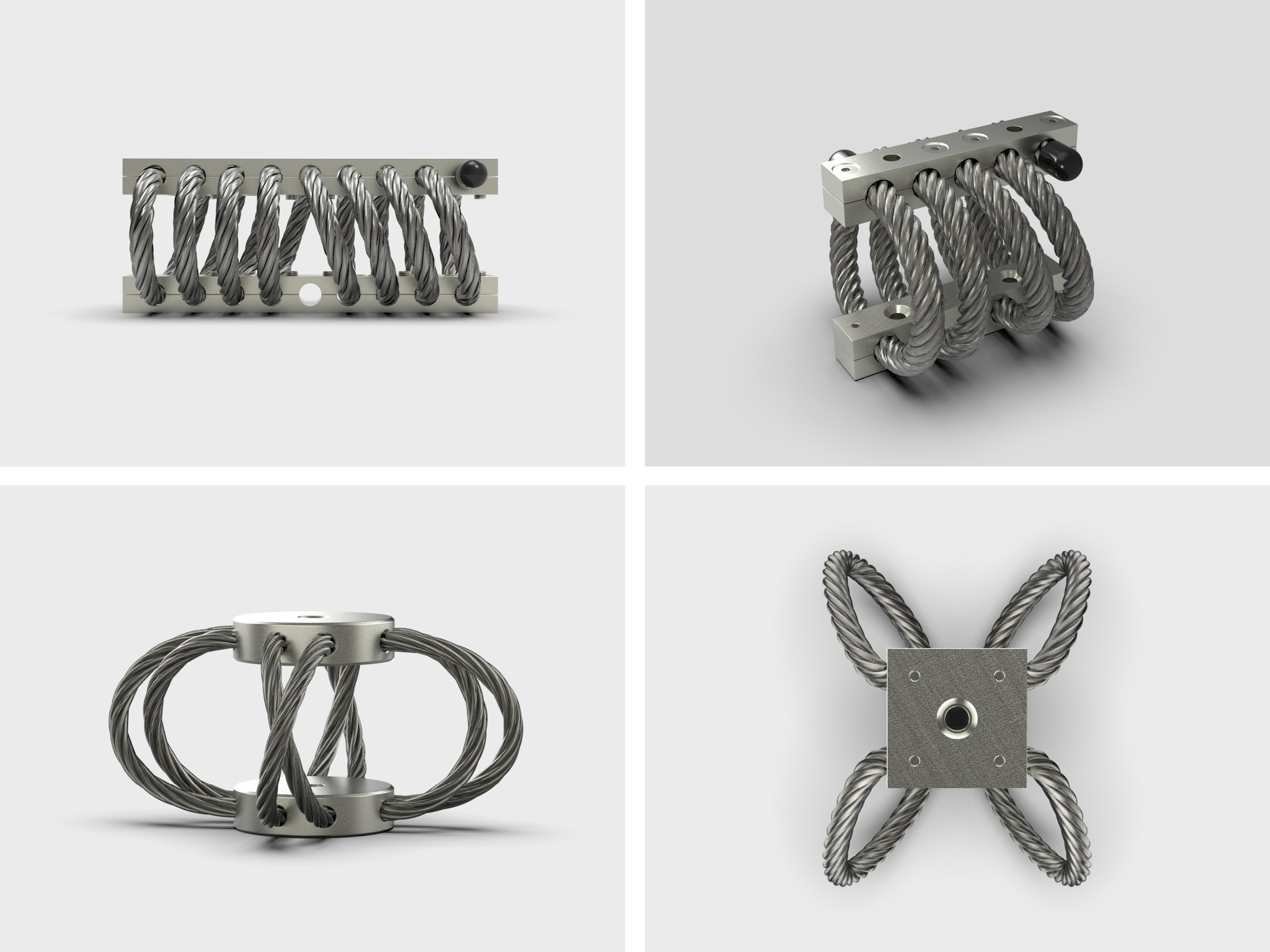
Stainless Steel Wire Rope Isolators —
- These isolation systems are adequate to meet the requirements of MIL-S-901D and MIL-STD-167.
- Can be easily tuned for a wide range of payloads and target/deck frequencies
- Stainless steel construction can hold up under the most severe marine environments.
- They perform extremely well under both compression and tension loading.
- They also have the capacity to provide protection in three-axes.
- Because they are not flammable, there is no negative consideration regarding whether they are certified or qualified for shipboard use relative to MIL-STD-2031 or MIL-M-17185.
Piston/Shock Absorber Style Isolators —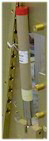
- Primarily used to isolate internal sub-assemblies from a hard mounted external enclosure
- They can be effective in the single axis for which the piston is oriented.
- They are often used as the primary means for supporting the load of an internal sub-assembly
- Complete 3-axes isolation protection can be provided when used in conjunction with secondary isolators.
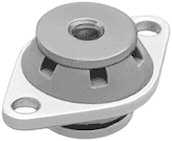 Composite Material Only Isolators —
- Primarily used to reduce the amount of structure-borne noise transmitted from electronic equipment into the surrounding structure or ship’s hull
- Can be used for extremely light payloads
- Pure rubber, rubber-like, fluid-filled or similar composite materials can lose their resiliency and isolating characteristics if over-compressed.
- Generally not used for heavier payloads demanding the full level of shock and vibration protection required by MIL-S-901D and MIL-STD-167
There are a few exceptions where composite material isolators are used for extremely heavy payloads such as motor generator sets. They are typically not found on electronic enclosures because of their bulk size. These types of isolators are generally designed for isolation in the vertical (load bearing) axis. While this is desirable for isolation of structure-borne noise, they will likely provide inadequate protection against external shock/vibration energy imposed in 3 axes. Note: See WARNING above.
Hybrid Isolators —
- These isolation systems can be adequate to meet the requirements of MIL-S-901D and MIL-STD-167 for some applications. Note: See WARNING above.
- CAUTION: Some suppliers of hybrid isolation systems claim their equipment provides universal protection over a wide range of frequencies. As discussed above under attenuation/dampening, this can’t be true. Even hybrid isolation systems using composite material must be tuned for the payload weight and deck frequency required of the application.
- CAUTION: Hybrid isolators may or may not provide equal or adequate isolation in 3-axes. In order to obtain adequate 3-axes protection, a larger number of hybrid isolators may be required to be installed in such a way as to provide true isolation in 3-axes. The very design of hybrid isolators precludes them from providing equal isolation in all 3 axes.
Isolators: Additional Considerations
Size — There are two issues involving the physical size of isolators that must be discussed.
- First, taller isolators take up significantly more vertical space leaving less space available for the electronic equipment enclosure. This can be especially important when installing replacement equipment into existing platforms where the available envelope is rigidly defined.
- Second, using taller isolators generally results in significantly larger back/forth movement for an enclosure subjected to shock and vibration excitation forces. The range in movement, often referred to as SWAY SPACE, is often a critical technical performance requirement.
Isolation systems must not only be designed to optimize enclosure protection for the payload and target deck frequency of interest, they must also provide enough stiffness and rigidity to prevent the enclosure from striking adjacent enclosures, bulkheads or other equipment by way of excessive sway space movement.
Individuals selecting isolators must confirm the Sway Space performance (given payload and frequency) to ensure enclosures don’t strike other objects under load, which could damage such equipment or impart excessively large G-loads on the electronics, essentially short-circuiting the isolation system. The taller the isolation system, the more difficult the task of meeting the Sway Space requirement. All things considered, compact isolators conserve vertical space and achieve better control of Sway Space.
Durability — Isolation systems in shipboard and marine environments are often exposed to heat, salt water, vibration and various solvents and petroleum compounds.
- Stainless steel isolators are proven to be unaffected by these harsh conditions.
- Some composite material isolators have been found to deteriorate and break down when subjected to these conditions. Not only will this affect the isolator performance relative to shock/vibration (MIL-S-901D and MIL-STD-167), it also imposes an inspection and replacement burden on the U.S. Navy.
- The life-cycle costs associated with any inspection and replacement burden associated with use of composite material isolators should be factored into any cost-value based acquisition decision.
Cost and Value — Certainly the cost of an isolation system is a consideration in developing an enclosure design.
- Internally mounted isolation systems, such as the piston/shock absorber style, often require extensive modification to the structure of an enclosure and can be quite expensive.
- As payload increases, the strength of the isolation system must also increase. For Stainless Steel Wire Rope isolators, this often requires only minor adjustments to the coils with little or no visible change in the isolator profile.
- For composite material isolators which have less strength individually, this can result in adding a large number of composite isolator mounts in order to support the required payload. This can significantly increase the cost.
While the cost of an isolation system is not insignificant, the cost associated with failing shock/vibration testing on either the light or medium weight shock table or floating shock platform (barge) can be staggering on several levels.
- First, the costs of the testing itself is at least doubled, since the failed unit will need to be assessed, redesigned, modified and tested again until the requirements of MIL-S-901D and MIL-STD-167 are satisfied.
- Second are the costs associated with program delays since enclosure integration and shipboard installation can’t begin until the enclosure and isolation system are qualified.
- Third, damage to the enclosure provider’s business reputation from a failed product is incalculable both in terms of continued participation on the existing program and potentially lost opportunities on future programs.
The most important aspect of an isolator system is that it performs to the standards outlined above. Purchasing the right isolation system for the application instead of what might appear to be trendy is the best value decision.